Digital filters are used to emphasize or de-emphasize frequencies present in waveforms. For example, low-pass filters preserve low frequencies and reject high frequencies.
Applying a filter to an input waveform results in a "response" output waveform.
Igor Pro® can design and apply Finite Impulse Response (FIR) and Infinite Impulse Response (IIR) digital filters. Each one can implement a filter that passes or rejects bands of frequencies, but the mathematics and implementations differ significantly.
Other forms of digital filtering exist in Igor, significantly the various Smoothing operations, which includes Savitzky-Golay, Loess, median, and moving-average smoothing.
Using the Convolve operation directly is another way to perform digital filtering, but that requires more knowledge than using the Filter Design and Application Dialog discussed below.
The Igor Filter Design Laboratory (IFDL) package can also be used to design and apply digital filters.
Finite Impulse Response Filters
"Finite Impulse Response" means that the filter´s time-domain response to an impulse (or "spike") is zero after a finite amount of time:
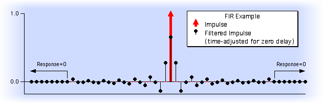
FIR filters have a very useful property: they can (and usually do) exhibit linear phase shift for all frequencies, a feat impossible for an analog or IIR filter. This means that the time-relation between all frequencies of the input signal is undisturbed; only the relative amplitudes are affected. (This is particularly important when processing television signals to keep the color signal aligned with the brightness signal).
When comparing the input and output of FIR-filtered signals, it is usual to shift the input or output in time to reduce linear phase to zero phase as in the graph shown above. When this is done, you can see that the filter´s output is changing before any input signal has arrived! This is sometimes referred to as "acausal filtering".
Igor implements FIR digital filtering primarily through time-domain convolution using the Smooth or FilterFIR commands.
The Smooth operation implements pre-defined low-pass filters whose coefficients are created algorithmically from only a few user-specified parameters. See Smoothing for graphs of the frequency responses of these filters (the phase response is uniformly zero because the filtering is acausal).
FilterFIR convolves data with user-supplied filter coefficients to implement any kind of FIR filter, low-pass, high-pass, band-pass, etc.
Design of the FIR filter coefficients used with FilterFIR is most easily accomplished using the Filter Design and Application Dialog or the Igor Filter Design Laboratory.
The FilterFIR command itself can also design simple filters and output the filter coefficients.
Low-pass to High-pass Conversion
Even lacking IFDL, one way to apply a high-pass filter a signal is to subtract a low-passed signal from the input signal. You can do this with Igor's wave assignments.
Another slightly faster way is to create high-pass filter coefficients for FilterFIR using coefficients formed by subtracting low-pass filter coefficients from an impulse:
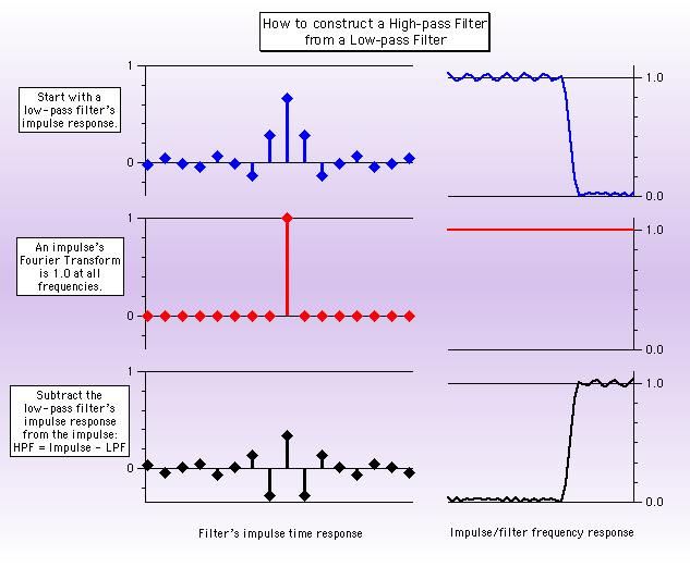
Where do you get the low-pass filter coefficients to start with? By smoothing an impulse!
Here are Igor commands which implement and apply a high-pass filter:
Make/O/N=19 impulse=0; impulse[9]=1   // Make an impulse at center (9 zeroes before, 9 after)
Duplicate/O impulse, smoothedImpulse  //   with room for smoothed response.
Smooth 5, smoothedImpulse             // Form impulse response of Smooth 5.
Duplicate/O impulse, coefs            // Storage for high-pass coefficients.
coefs= impulse - smoothedImpulse      // High-pass = Impulse - Low-pass.
FilterFIR/COEF=coefs, myData          // Apply high-pass filter.
Infinite Impulse Response Filters
The response of an IIR filter continues indefinitely, as it does for analog electronic filters that employ inductors and capacitors:
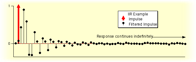
IIR filters are more like real electronic filters because they are "casual": no output signal is produced until the energizing input signal has arrived.
IIR filters can realize quite sophisticated frequency responses with very few coefficients. The drawbacks are non-linear phase, potential for numerical instability (oscillation) when realized using limited-precision arithmetic, and the indirect design methodology (frequency transformations of conventional analog filter methods).
Igor uses two IIR implementations:
- Direct Form I (DF I)
- Cascaded Bi-Quad Direct Form II (DF II)
The IIR coefficients are represented in three forms:
- • DF I
- • DF II
- • Zeros and Poles form
You supply IIR coefficients to the FilterIIR operation along with the input waveform to compute the filtered output waveform. The format of IIR design coefficients differs between the three forms.
Filter Design and Application Dialog
The Filter Design and Application dialog provides a simple user-interface for designing and applying a digital filter. Choose Analysis->Filter to display it:
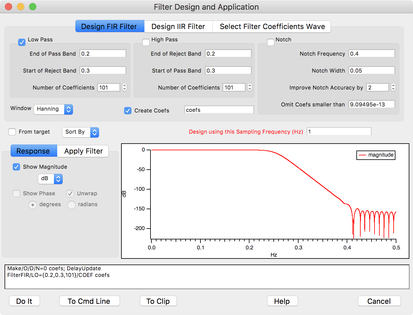
This dialog allows you to design a subset of the Igor Filter Design Laboratory (IFDL) filters. It is simpler and the filters are sufficient for most purposes.
You can use any combination of one low pass band, one high pass band, and one notch to pass or reject frequency components of the sampled data wave. By using both low pass and high pass bands you can create Band Pass and Band Stop Filters.
Applying an FIR Filter to Data
Click the Apply Filter tab to see the result of applying the designed filter to a waveform.
Select the input wave in the Input to Filter listbox and click either Auto-update Filtered Output checkbox or the Update Output Now button. This updates a preview of the filtered result:
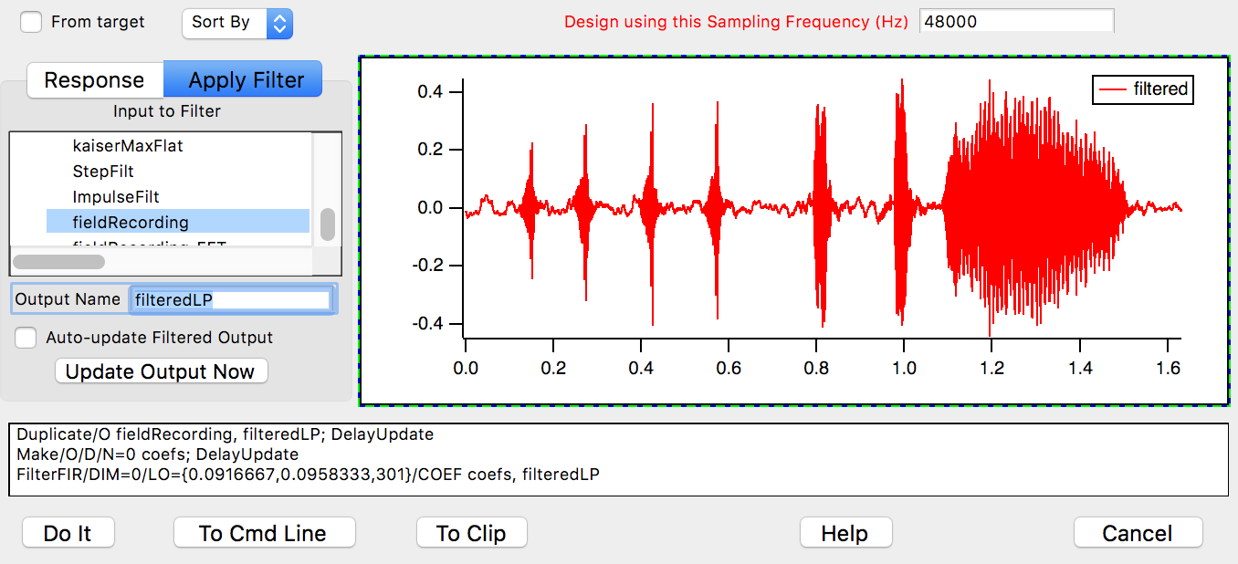
Click Do It to create a final output wave in the current data folder. You can set the name of the final output wave in the Output Name field. Here we used "filteredLP".
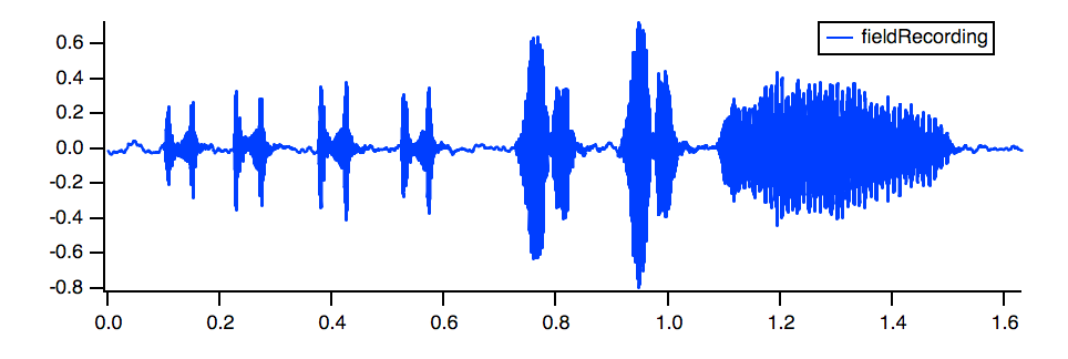
For comparison, here is the unfiltered fieldRecording:
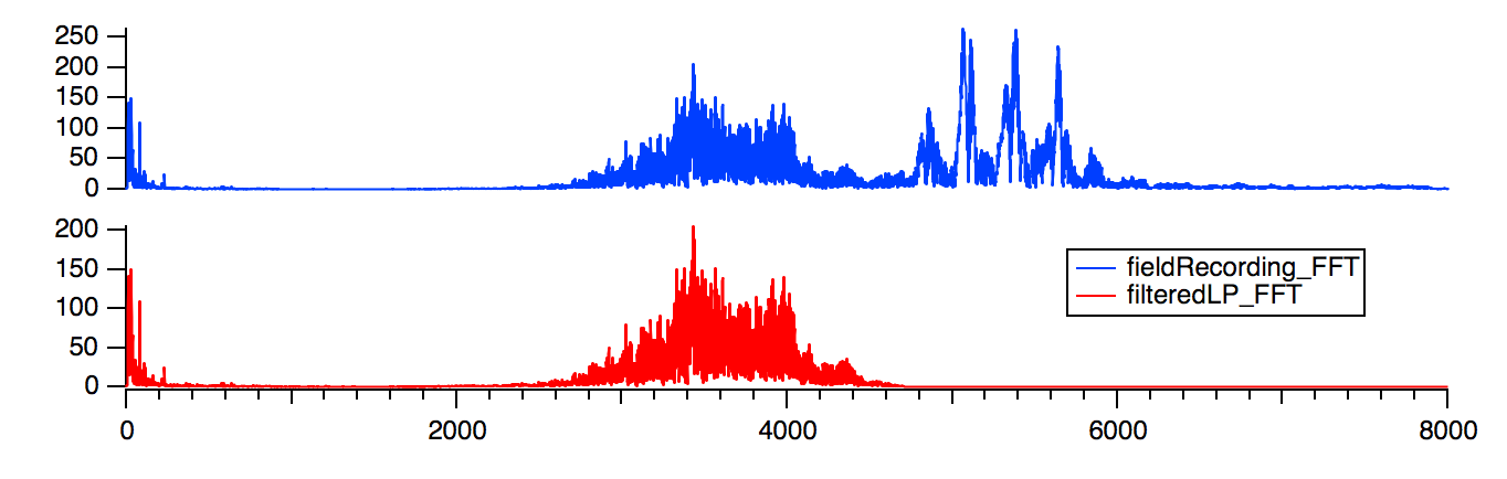
The preview in the dialog shows that the higher-frequency elements are removed in the filtered output. An FFT of the filteredLP result verifies the change:
References
- Terrell, Trevor J., Introduction to digital filters, Halsted Press/John Wiley & Sons, 2nd Ed 1988.

Forum

Support

Gallery
Igor Pro 10
Learn More
Igor XOP Toolkit
Learn More
Igor NIDAQ Tools MX
Learn More