Correct way to use opacity of markers in Gizmo


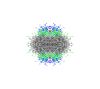
I'm displaying a dense cloud of points in a Gizmo window and I'd like the "darkness" of overlapping points to reflect the density of points in a location (as a projection towards the viewer). This code is a MWE of what I am doing.
SetRandomSeed(0)
Make/O/N=(100,3) aaa=gnoise(1)
KillWindow/Z gz0
NewGizmo/N=gz0
AppendToGizmo/N=gz0/D Scatter=aaa,name=scatter1
ModifyGizmo/N=gz0 ModifyObject=scatter1,objectType=scatter,property={ size,0.4}
ModifyGizmo/N=gz0 ModifyObject=scatter1,objectType=scatter,property={ color,0,0,1,0.5}
ModifyGizmo/N=gz0 insertDisplayList=0, attribute=blendFunc0
AppendToGizmo/N=gz0 attribute blendFunction={770,771},name=blendFunc0
ModifyGizmo/N=gz0 insertDisplayList=0, opName=enableBlend, operation=enable, data=3042
Now overlapping points of alpha=0.5 sum to 1 for some of the points. When the cloud is rotated so that a third point obscures the first pair, the third point is now displayed as though it is alpha = 0.5 on a white background. I'd like the behaviour to be similar to markers on a 2D graph window where overlapping markers max at 1.
The problem does not seem to be the angle the Gizmo is viewed at... my guess is that the GL_Blend function settings are not correct. I've tried changing them but can't get the desired effect. My question is: what is the best way to do this so that the density of points can be appreciated?
Thank you for any help.
I hope AG weighs in for the final word, but in the meantime I suggest this is an intrinsic issue with Gizmo/OpenGL. It has to do with objects' order in the display list vs the orientation they are viewed. The simplest example is to create a sequence of uniformly translated spherical objects (with surface normals, color alpha, blend function, etc.). When viewed in two opposite directions along the translation axis, the alpha overlap behavior you are after is present; in the opposite direction it is not. Your scatter markers and positions present an even more complicated (and possibly more limited) situation.
September 18, 2018 at 06:42 am - Permalink
Thank you for the reply. Yes, that makes sense. In my example (and in my dataset) the order of the points is not sorted from back to front.
For the benefit of anyone else reading this: to help me understand, I made a wave with only 5 points with x,y = 0 z = p. Viewed from the front, the markers behave as desired. From the rear, not so. Exactly as s.r.chinn said. If I change the order of the points e.g. by reversing the z co-ordinates, the markers do not behave as desired when viewed from the front. So the order in which the markers are drawn is important. I knew this but somehow I needed this explanation to help me see what was going on.
I need to rethink how to display these markers.
September 18, 2018 at 07:36 am - Permalink
Comments:
1. Spheres are not ideal markers for this application because they have a closed surface so you really need to consider 4 sides.
2. There is no way to implement this (that I can think of) that does not involve performing some kind of depth sorting.
I would recommend looking at the example in File Menu->Example Experiments->Visualization->Advanced->DepthSortingDemo.
3. You might be able to simplify your calculations using disk markers together with a rotation wave that would be recomputed on each change in Gizmo orientation in order to keep the disk axis in the direction of the viewer.
A.G.
September 18, 2018 at 12:46 pm - Permalink