Plotting Confidence Image(?) of an Ellipse Fit


I have converted a lengthy set of Matlab codes to implement the Szpak et al. (2015) method of fitting an ellipse (an approximate maximum-likelihood method), and from it I get the parameters and standard error on each parameter. What I would like to do is plot the ellipse and plot the confidence region around that ellipse to be able to visually see how good of a fit it is.
The problem with doing this for an implicit function, such as an ellipse, is that it's not as simple as x ± sigma_x. For example, picture a circle. You have uncertainty in {x0,y0,D}. One could naïvely just plot three circles: the fit, the fit minus sigma on each parameter, and fit plus sigma on each parameter. But, what about {x0-sigma_x0, y0+sigma_y0, D+sigma_D}? And for an ellipse, where you have five fit parameters {x0, y0, major, minor, angle}, this gets complicated.
So what I'm thinking is to create a matrix scaled to cover the domain I'm interested in displaying, and somehow test every position in that matrix and return a value that is equal to the probability it's on the ellipse fit. For example, any cell in the matrix with a center value that is actually on the ellipse I fit would have a value of 1. If it's within the 1-sigma range, it would be >0.683... (assuming Gaussian-distributed noise). Then, I could overlay contours on the matrix and so effectively visualize the confidence region.
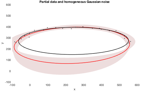
So ... anyone have any idea how to do this? Igor's implicit function support isn't great (sorry folks!), but even in Matlab the guy who wrote the paper on this had to sort of hack it to display a confidence region. I've attached a screenshot of *his* solution to example data, where the black dots are data, black ellipse is a direct fit to an ellipse which is biased (Igor's ellipse fit is even older than the biased direct fit and I have found it to give just as poor results with data like this), red ellipse is the new technique by Szpak and colleagues, and the red region is the 68.3% confidence region. As you can see, it is NOT a simple function because of the way the fit parameters interplay. While being able to do something like the screenshot is something I'd be willing to settle for, my idea above would also allow that and would be a special case (simply filling the image matrix as a binary 0 / 1 for anything ≶ 0.683...).
So, yeah ... any ideas on either (a) how to do what I thought of above, but how to actually go about testing points for how many sigma-away from the ellipse fit they are, or (b) a different method altogether to accomplish this?

Forum

Support

Gallery
Igor Pro 10
Learn More
Igor XOP Toolkit
Learn More
Igor NIDAQ Tools MX
Learn More
Okay, I was able to hack the hacked Matlab solution, though I'm just assuming that it works. The Matlab solution doesn't return values of sigma, but in terms of chi-squared values, so I used Igor's StatsChiCDF for 5 degrees of freedom to convert to p-values and I think this is what I need ... sort of. P-values aren't quite the same as sigmas, but if I have nothing else, this will work.
July 30, 2018 at 10:51 am - Permalink
This is pretty interesting- could you post your code and an example dataset?
July 31, 2018 at 11:15 am - Permalink
I will when I finish optimizing it. I found two bugs in the confidence calculations (I had hard-coded some values that shouldn't've been) and there are some loops that can be threaded (code takes ~seconds to run on 1000 points, which is pretty long).
July 31, 2018 at 11:23 am - Permalink
Probably the most robust way of doing this would be with MCMC sampling of the posterior distribution for the model parameters. Each sample would give a separate generative curve, you could plot a number of those with an alpha value of say, 0.05. In the areas which are more common the curves would overlap and become more opaque.
Not sure how to do this with Igor though.
July 31, 2018 at 05:51 pm - Permalink
In reply to Probably the most robust way… by andyfaff
astrostuSounds great "in theory," as the saying goes. Lemme know how to go about it and I'll try. :)
July 31, 2018 at 08:03 pm - Permalink
Attached is my current code. It's about as efficient and multi-processor-aware as I know how to make it. The variable/wave names are wildly inconsistent because of the direct port from Matlab and then my attempt to make things that I understood a bit clearer. Runs in under a second unless you have it filling in the p-value matrix, which takes much longer (2.5 seconds on my computer, the way I have it set up now).
August 2, 2018 at 11:37 am - Permalink
Are you willing to post your ellipse dataset? I'd like to play around with fitting it.
August 3, 2018 at 11:43 am - Permalink
In reply to Are you willing to post your… by johnweeks
astrostuThe fake data is generated each time you run the line noted in the procedure window. The 8th call in there to the ellipseforModelling() (right now 0.05) is ±Gaussian noise. Is that what you're asking?
August 3, 2018 at 11:45 am - Permalink
I found two insidious bugs that hadn't come up before, plus I found two potential issues. The two bug fixes are: "grad" is 6x1, not Nx1; and the first data noise function uses unnormalized data, not normalized.
The first issue I couldn't solve is precision. I had back-and-forths with WaveMetrics years ago about precision and at the time everything was fixed by declaring waves with /D. I know you folks take precision very seriously, so I don't comment on this lightly. I mentioned above that this code is ported from Matlab, and so basically every step I compared with Matlab's output to ensure I was doing it right. There's a part, though, that the two start to diverge, and it has to do with two lines that are MatrixOP lines. I tried running them by declaring the matrices first as /D, and then not declaring them first. Both times yielded identical results in Igor, but they were different at the ~15th-16th decimal point from Matlab. I confirmed by running "digits" that Matlab was running in double/32-bit mode. Going in, all arrays/waves/variables were the same to the 16 digits I could display. Seems minuscule, but since this is an iterative code, it builds up and by the second iteration, which is the third output, they diverged at the ~4th–6th decimal point. Which gets more significant.
The second issue I couldn't solve is something in my threading that I can't track down. It's very weird: I'm on an 8 core machine, and when nthreads = 8, I get different results than when nthreads = 1, 2, 3, ..., 7. No idea why, but since <8 threads gets me the same (to ~4 sigfigs) as Matlab, and 8 gives me different (at ~2nd sigfig), I'm leaving it at <8 right now and leave it to Future Stuart to figure out.
August 4, 2018 at 02:43 pm - Permalink
A quick look shows that many of your Make statements lack the /D flag. That will make single-precision waves
August 6, 2018 at 09:39 am - Permalink
In reply to A quick look shows that many… by johnweeks
astrostuNope: None of the Make statements in the AML (as opposed to DIR1 and DIR2) code is withOUT /D except for the initial DIR fit within it that acts as a seed, and those values are then stored to a /D wave. So, that's not it. (I just did a search.)
August 6, 2018 at 09:42 am - Permalink
I tried Igor's implicit fit using this fitting function:
Using a starting guess of
I got this result:
•FuncFit/ODR=3 FitEllipse2, EllipseODRCoefs2 /X={Ellipse_X_Data, Ellipse_Y_Data}/XD={ellipseXFit,ellipseYFit}
Fit converged properly
EllipseODRCoefs2={0.89244,0.51816,5.006,2.9951,1.3808}
V_chisq= 0.0180663;V_npnts= 100;V_numNaNs= 0;V_numINFs= 0;
W_sigma={0.0489,0.0232,0.0424,0.0675,0.0233}
Coefficient values ± one standard deviation
a =0.89244 ± 0.0489
b =0.51816 ± 0.0232
x0 =5.006 ± 0.0424
y0 =2.9951 ± 0.0675
theta =1.3808 ± 0.0233
•print EllipseODRCoefs2[4]*180/pi
79.1147
I'm not sure why my angle is close to 80; a plot shows that it oriented correctly on XY plane. Perhaps this is angle relative to the X axis, with positive clockwise. That would mean that my fit didn't reproduce the angle as closely as your fit, but a plot shows that overall my fit comes closer to the "perfect" curve (see the attached image).
This test function:
gives a time to fit of about 0.075 seconds. Knowing the real coefficients, of course, and using them as starting guess is sort of cheating...
In any case, it does suggest that an ODR-based implicit fit might be worth a consideration.
In your original posting, you said
Does my example change your mind at all?
August 6, 2018 at 11:09 am - Permalink
A note about the graph attached to my previous post: the dashed line is a contour of a matrix image generated like this:
This is an easy way to generate a curve from the implicit fit function. Otherwise you would have to generate curve points using something like FindRoots.
August 6, 2018 at 11:13 am - Permalink
Here's my copy of astrostu's experiment file, along with my ODR=3 fit.
August 6, 2018 at 11:21 am - Permalink
The problem, as you stated, is you're cheating: You are feeding the fitter the true ellipse parameters.
If instead I feed it parameters from a blind method, like the Fitzgibbon one (and after fixing your angle to go counter-clockwise from the x axis, which is how I have it defined), then I get:
In comparison:
And to remember fairness: Szpak uses the DIR method as a first-guess, too.
So it looks to me as though Igor's ODR did a better job in this instance of getting the center position, but the AML did a much better job at getting the axes and tilt.
Let's make it harder: I used my ellipseforModeling() program to draw points between 0° and 110°, and with 0.01 gnoise added. (If you do this test yourself, results will obviously vary due to the gnoise):
Igor has no idea what it's doing here. I then fed it the true, ideal parameters (as you originally had it), and it still gave a nonsensical result, similar to the above.
The thing is, in my work with impact craters, most codes give (almost) the same, perfectly fine results when I have a nearly complete crater rim. But, it's when I have those highly eroded crater rims where I have just a small part of the ellipse that the codes diverge wildly. This specifically came up when I was trying to apply my ellipse fits to a method to fit the shadow cast into a crater by the crater rim: By having good ellipse-fit parameters, you can calculate the crater depth by fitting that shadow. But by definition, that shadow is only a small part of the ellipse, and that's when I discovered that the Fitzgibbon "Direct / DIR" method was giving me horrible results and started me down this path.
That's a really long way of responding to your question of, "Does my example change your mind at all?" about my statement that Igor's ODR provides bad fits: No, it doesn't in cases where it matters. Where, "where it matters" here means where I have VERY partial, slightly noisy data that needs to be fit to an ellipse.
If you think you can make Igor's ODR behave better when you only have, say, 1/4 of the arc, I'm all ears! (or, eyes)
Note that I also tried a completely different technique this weekend since I found Matlab code for it: SVD (singular-value decomposition). It's another blind method, and it did even worse than the DIR method.
August 6, 2018 at 11:51 am - Permalink
For instance: https://www.google.com/mars/#lat=17.175696&lon=164.781084&zoom=8&map=in… and then click the "Infrared" box near the upper-left if it's showing you a color topography image instead. That crater in the middle has a partial, maybe 1/3 rim on its left side. One could perhaps assume that the wrinkle ridge to the right is the right side of the rim, but there are crater folks who'd cry bloody murder if you did that. So I have 1/3 of a rim to fit, and even that 1/3 has gaps in it.
Or: https://www.google.com/mars/#lat=16.567233&lon=162.749986&zoom=9&map=in… . You have an arc that spans maybe 1/4 of a possible crater rim, from maybe 90° to 180° clockwise from North. Perhaps a few degrees of arc around 20°. Very partial.
August 6, 2018 at 11:59 am - Permalink
Wow. The DIR1 fit is truly terrible. The fact that your Szpak method can still get a good fit is pretty impressive.
So I used the built-in sin fit to fit the X and Y data and generated an initial guess using the amplitude, y0, and phase from each fit to come up with a better initial guess. That allowed the ODR fit to get a solution. Picture attached.
So I see your point- Szpak can get a fit with truly awful initial guess. That's impressive.
But perhaps you statement "Igor's implicit function support isn't great (sorry folks!)" would be more accurate if you said that the Szpak method is superior to least-squares methods. Igor's support for implicit fits isn't bad, but for this particular problem there is a more robust method.
August 6, 2018 at 01:53 pm - Permalink
Okay, I'll revise my statement to this: Igor's method for implicit fits uses an orthogonal distance regression (ODR), which is a good fit provided a reasonable initial guess and well behaved data. If you don't have a good initial guess, and you have partial and/or noisy data, ODR algorithms are not reliable for fitting implicit functions with several fit terms (e.g., ellipses, as opposed to circles).
But, that's a much longer statement, though I did not mean anything personal when I said Igor's ODR isn't good ... it's just the algorithm, not Igor!
August 6, 2018 at 01:56 pm - Permalink
That said: I'm actually presenting this work this week at a crater conference. Can you post your code on how you got your initial guesses? I'd like to show examples of different algorithms and this way can include a DIR, SVD, ODR, and AML.
And science-wise, those tilt angles are important! Direction of impactor, tracers for how planets may have wobbled in the past, and other things. So, it's not just an academic/theoretical problem.
August 6, 2018 at 01:59 pm - Permalink
I think we're on the same page now. As for the longer and less personal statement, that can be just as important as the ellipse angle, if the problem is evaluating software that you might buy. I'm really interested in having people want to buy Igor :)
I don't have code for the sin fit method, it was pretty ad-hoc, but based on real math :) I have to admit that I did the sin fits using the Curve Fit dialog while looking at the data, so I was able to give a reasonable number for the sin fit /B input, which gives the guessing code a hint as to the frequency. But since the data will never include more than 2*pi, that shouldn't be to hard to automate.
Then the amplitude of the fit to the X data is half the major/minor diameter, amplitude of the fit to the Y data is half the minor/major diameter, the y0 of these fits gives you an estimate of X and Y center. The phase angle should be related to an estimate of the ellipse angle. You get two estimates, one from X and one from Y- and here's the part where actual code that can run unattended might break down- one of those will be a better estimate because it is fit from a part of the sinusoid that constrains the phase better. Deciding which is which could be tricky, though I see now that I actually use the one that had smaller uncertainty.
You don't need the frequency from the fit, so you don't need to know ahead of time what fraction of the ellipse is represented by the data. That's the only fit output that depends on wave scaling/X values, and happily it doesn't matter!
Have a good time at your conference.
August 6, 2018 at 02:22 pm - Permalink
In reply to I think we're on the same… by johnweeks
astrostuUnderstandable, but it doesn't look like I can modify the original post to add the asterisk and explain more.
I will work on implementing your technique for guessing (who knows: it might be better than using the DIR1 as a seed), but if you have a few minutes and it's still in your head and you've nothing better to do today ... consider writing up a code snippet for me. :)
Also, I've gotten in touch with Szpak and his still-living coauthor (another one has died) about implementing his algorithm with constraints on the various parameters. If y'all are interested, I'll give you whatever license you want to use the code (I'm sure you'll clean it up) in a future release of Igor ... though it's likely a small audience who needs to do this kind of fit to this kind of data.
August 6, 2018 at 02:36 pm - Permalink
Don't worry about the original post. I'm happy :)
Pursuing your request for a code snippet has forced me to think a bit more about my guess method. I concluded that I got lucky, and implicitly took advantage of some of the characteristics of the problem you posed.
Your fake data sets are sampled at evenly-spaced values of theta, so my fits actually work, and have relevance to the problem. If you don't have evenly-spaced theta, then you don't have any idea how to do the fit, and you're back at the beginning again.
Sorry to get you all excited.
August 6, 2018 at 04:47 pm - Permalink