Fit concentric rings

Hi,

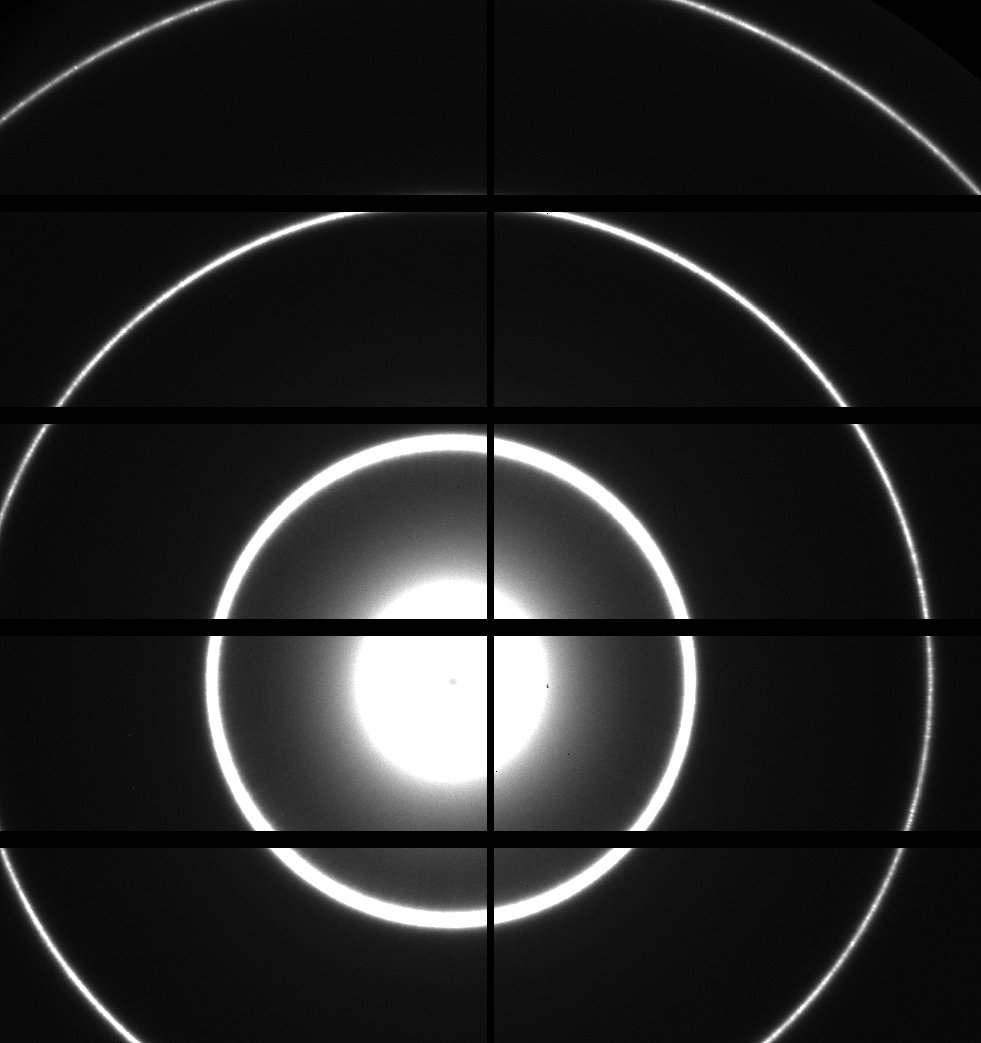
I would like to fit a 2D gray scale image with concentric rings and get the radii and center of these rings. The radii of these rings are in a ratio of 1:2:3.

This 2D image is hard to be converted to a binary image with rings.

I found that the 2D Gauss fit and polygonal fit work on the gray scale images without converting them to binary images.
How can I build a fit function of 3 concentric circles to fit my image?

The gray scale image is attached as a text file.

A capture of the gray scale image. The image data I need to fit.

I loaded the text file you linked in your message; it is not at all like the image you posted. I have attached an image of the loaded data. It looks like in the process of saving the text file the data was clipped. You may be able to load the image data you posted directly without converting to a text file.

Without being able to see the form of the rings, it's hard to say how to write a fitting function for that data. Once you manage to get the image data into Igor intact, I would use Image->Line Profile to inspect the form of the rings to guide the search for a suitable fitting function.

If you can describe where this image is from, it may be that someone familiar with similar data may have more targeted advice.

Graph0.png

FWIW I could import the data and (after contrast adjustment) see the rings.

OK, sjr51- you win this time :)

After taking the log of the data (and ignoring NaNs from log(0)) I stand corrected. 

And now- using Rainbow color table and reversing the colors the rings are definitely there.

If you do a line profile over the image you can see the shapes of the peaks- they look rather Lorentzian. They have pretty sharp tops and long tails. The middle and the saturation of the sides of the middle will complicate things a bit.

I am going to go out on a limb and hazard a guess: the most important variation is radial (this is some type of radially averaged diffraction pattern ... perhaps TEM or scattering or ... ???). In this case, I would find the center of the image, make a radial slice through it, and fit the resulting line profile. As the next step, I would slice a few radial lines, average them, and improve the S/N for fitting. As the final step, I would take an 360 degree rotation around the center, sum all slices for the best S/N, and fit that resulting profile.

When the theta variation is also important, I might start with the radial slice as the guess in the radial parameters, hold those constant, and fit a 3-D profile that includes only the theta variation. But ... Dealing with the interruptions from the grid lines will be a real PITA in this case.

I see that the grid lines are places where the image has Z value of -1. You can deal with the grid lines by creating a mask wave for the fit the masks out any place in the image that has a negative number:

Duplicate Image, ImageMask
ImageMask = Image[p][q] >= 0

Getting a function that will fit the radial profile may be a way to get started. Do you have any notion of a function that describes your rings?

Elliptical rings would make it more complicated but not by a lot.

In reply to by jjweimer

jjweimer wrote:

I am going to go out on a limb and hazard a guess: the most important variation is radial (this is some type of radially averaged diffraction pattern ... perhaps TEM or scattering or ... ???). In this case, I would find the center of the image, make a radial slice through it, and fit the resulting line profile. As the next step, I would slice a few radial lines, average them, and improve the S/N for fitting. As the final step, I would take an 360 degree rotation around the center, sum all slices for the best S/N, and fit that resulting profile.

When the theta variation is also important, I might start with the radial slice as the guess in the radial parameters, hold those constant, and fit a 3-D profile that includes only the theta variation. But ... Dealing with the interruptions from the grid lines will be a real PITA in this case.

Thanks for explaining the background. You guess is correct. The image is a 2D scattering pattern from a standard chemical compound. I need to know the center and radii of these rings to perform a series of other reduction process.

The problem is

1. the rings are not always circles, they could be ellipses.

2. the center sometimes outside the image.

3. and there are always grid lines (value = -1 or -2) that are the space between detector panels.

I have tried to make a dummy binary image with rings (in ring value = 1, out ring value = 0) and multiplied to the image I posted. The sum of the multiplied image will be a value showing the similarity between the dummy and real one.

Then, I change the radii and center of the dummy image and repeat the multiplication and sum process to find the biggest value, which should correspond to the most similar dummy image. However, this takes really a lot of time.

I hope that I can use fit functions or other better techniques to get the radii and center.


In reply to by johnweeks

johnweeks wrote:

I see that the grid lines are places where the image has Z value of -1. You can deal with the grid lines by creating a mask wave for the fit the masks out any place in the image that has a negative number:

Duplicate Image, ImageMask
ImageMask = Image[p][q] >= 0

Getting a function that will fit the radial profile may be a way to get started. Do you have any notion of a function that describes your rings?

Elliptical rings would make it more complicated but not by a lot.


I have used for-loops to create the mask before. Your codes are really nice.

The fit function I want to use is attached. The rings have the same center and different radii.

My approach to fully automate this would be to pick the center of the image as a starting guess for the center of the circles. I would then extract a radial profile from that and use that radial profile to recreate the image. You can now use the difference between the real image and the recreated image to write a fit function and find the center of the circles and the radial profile, see the code below.

The nice thing about this approach is that you don't need to assume anything about your peak shapes, only that you have circular symmetry. You can then fit your peaks to the radial profile instead.

For my code to work your image has to be root:RawImage. The data should have no X or Y scaling.

The code only works with circular symmetry, but I'm sure you can add an extra fit parameter to make it work for ellipses as well.

Run CreateGraphs() first to display the data and then FindRadialCenter() to extract the radial profile and find the center of the circles.

Your raw data is full of NaNs and +/-INFs so CreateGraphs() first extrapolates what those values should be based on the nearest valid data points. The data before and after the correction will be displayed by CreateGraphs() together with the radial profile and the recreated image based on the radial profile.

Expect CreateGraphs() to take 10-20 seconds and FindRadialCenter() to take several minutes. I'm sure the code can be optimized, but I didn't care about that.

Function CreateGraphs()

    //  You need to copy your image to this location
    Wave OriginalRawImage=root:OriginalRawImage

    //  Works on a copy of the original image. I accidentially messed up the image and had to reload it a few times. Hence the copy.
    Duplicate/O OriginalRawImage root:RawImage/WAVE=RawImage

    //  Takes the logarithm of the image so the circles are visible
    RawImage=log(OriginalRawImage)
   
    //  Calculates the size of the image
    Variable ImageXSize=DimSize(RawImage, 0)
    Variable ImageYSize=DimSize(RawImage, 1)
   
    //  Make a copy of the raw image
    Duplicate/O RawImage, root:CorrectedImage/WAVE=CorrectedImage
   
    //  Extracts the positions of all NaNs and +/-INFs in the image
    Extract/FREE/INDX/O RawImage, BadPoints, NumType(RawImage)!=0
    Variable NumberOfBadPoints=NumPnts(BadPoints)
   
    //  Counts through all the bad points and replaces them one at a time with the average of the closest valid data points
    Variable i=0, ii=0, XPos=0, YPos=0
    for (i=0; i<NumberOfBadPoints; i+=1)

        //  Converts the index value to X and Y positions in the image
        XPos=Mod(BadPoints[i], ImageXSize)
        YPos=Floor(BadPoints[i]/ImageXSize)

        //  Searches for valid data points inside an increasing square centered on the bad point
        ii=1
        Do
           
            Duplicate/O/FREE/R=[Max(XPos-ii, 0), Min(XPos+ii, ImageXSize-1)][Max(YPos-ii, 0), Min(Ypos+ii, ImageYSize-1)] RawImage TempSmallImage
            Extract/FREE/O TempSmallImage, GoodPoints, NumType(TempSmallImage)==0
            ii+=1
        while (NumPnts(GoodPoints)==0)
       
        //  Replaces the bad point
        CorrectedImage[XPos][YPos]=Mean(GoodPoints)
    endfor


    //  Creates the radial profile
    Wave RadialProfile=CreateRadialProfileFromImage(CorrectedImage, 0.5*ImageXSize, 0.5*ImageYSize)
    Duplicate/O RadialProfile root:RadialProfile/WAVE=RadialProfile
   
    //  Creates the image created from the radial profile
    Wave ImageFromProfile=CreateImageFromRadialProfile(RadialProfile, CorrectedImage, 0.5*ImageXSize, 0.5*ImageYSize)
    Duplicate/O ImageFromProfile root:ImageFromProfile/WAVE=ImageFromProfile

    //  Creates the window with the images
    DoWindow/K RadialWindow
    NewPanel/K=1 /W=(50, 50, 1150, 1050) /N=RadialWindow
       
    //  Creates a vertical and a horizontal guide to help arrange the subwindows with the images
    DefineGuide /W=RadialWindow FH={FT, 0.5, FB}, FV={FL, 0.5, FR}

    Display/K=2 /HOST=RadialWindow /N=RawImageWindow /FG=(FL, FT, FV, FH)
    AppendImage /W=RadialWindow#RawImageWindow RawImage
    ModifyImage /W=RadialWindow#RawImageWindow RawImage, ctab= {*,*,ColdWarm,0}, ctabAutoscale=1, lookup= $""
       
    Display/K=2 /HOST=RadialWindow /N=CorrectedImageWindow /FG=(FV, FT, FR, FH)
    AppendImage /W=RadialWindow#CorrectedImageWindow CorrectedImage
    ModifyImage /W=RadialWindow#CorrectedImageWindow CorrectedImage, ctab= {*,*,ColdWarm,0}, ctabAutoscale=1, lookup= $""
       
    Display/K=2 /HOST=RadialWindow /N=ImageFromProfileWindow /FG=(FL, FH, FV, FB)
    AppendImage /W=RadialWindow#ImageFromProfileWindow ImageFromProfile
    ModifyImage /W=RadialWindow#ImageFromProfileWindow ImageFromProfile, ctab= {*,*,ColdWarm,0}, ctabAutoscale=1, lookup= $""

    Display/K=2 /HOST=RadialWindow /N=RadialProfileWindow /FG=(FV, FH, FR, FB) RadialProfile
end


Function FindRadialCenter()
//  Finds the center of the image by minimizing the deviation between the raw image and the image created from the radial profile
//  X and Y scaling of image must both be 1

    Wave CorrectedImage=root:CorrectedImage
   
    //  Calculates the size of the image
    Variable ImageXSize=DimSize(CorrectedImage, 0)
    Variable ImageYSize=DimSize(CorrectedImage, 1)

    //  Use the center of the image as a starting guess for the center of the radial profile
    Make/O/D/FREE CenterPosition={0.5*ImageXSize, 0.5*ImageYSize}
   
    //  Converts the raw image into a 1D wave
    Duplicate/O/FREE CorrectedImage, CorrectedImage1D
    Redimension/D/N=(NumPnts(CorrectedImage1D)) CorrectedImage1D
   
    //  Does the actual fit. The epsilon wave is needed for the fit to work. It might make sense to do a crude initial fit and then a finer final fit
    Make/O/FREE/D EpsilonWave={0.01*ImageXSize, 0.01*ImageYSize}
    FuncFit/Q FitRadialCenter, CenterPosition, CorrectedImage1D /E=EpsilonWave

    //  Saves the radial profile
    Wave RadialProfile=CreateRadialProfileFromImage(CorrectedImage, CenterPosition[0], CenterPosition[1])
    Duplicate/O RadialProfile root:RadialProfile
   
    //  Saves the image created from the radial profile
    Wave ImageFromProfile=CreateImageFromRadialProfile(RadialProfile, CorrectedImage, CenterPosition[0], CenterPosition[1])
    Duplicate/O ImageFromProfile root:ImageFromProfile
end


Function FitRadialCenter(pw, yw, xw) : FitFunc
//  Finds the center of the image by minimizing the deviation between the raw image and the image created from the radial profile
//  X and Y scaling of image must both be 1
WAVE pw, yw, xw
   
    Wave CorrectedImage=root:CorrectedImage

    //  The radial center
    Variable CenterX=pw[0]
    Variable CenterY=pw[1]
   
    //  Creates the radial profile based on the chosen center
    Wave RadialProfile=CreateRadialProfileFromImage(CorrectedImage, CenterX, CenterY)
   
    //  Recreates the image from the radial profile
    Wave ImageFromProfile=CreateImageFromRadialProfile(RadialProfile, CorrectedImage, CenterX, CenterY)
   
    //  Converts the image into a 1D wave
    Redimension/D/N=(NumPnts(ImageFromProfile)) ImageFromProfile
   
    Print(" ")
    Print("CenterX = "+Num2Str(CenterX))
    Print("CenterY = "+Num2Str(CenterY))
   
    //  Copies the values into the fit result
    FastOP yw=ImageFromProfile
end


Function/WAVE CreateRadialProfileFromImage(CorrectedImage, CenterX, CenterY)
//  Extracts the radial profile of the image for the center coordinates given
//  X and Y scaling of image must both be 1
Wave CorrectedImage
Variable CenterX, CenterY

    //  Calculates the size of the image
    Variable ImageXSize=DimSize(CorrectedImage, 0)
    Variable ImageYSize=DimSize(CorrectedImage, 1)
   
    //  Calculates the necessary length of the radial profile wave as the distance from the center to the furthest corner of the image
    Variable MaxCenterToCorner=sqrt((Max(CenterX, ImageXSize-CenterX-1))^2+(Max(CenterY, ImageYSize-CenterY-1))^2)
   
    //  Creates the waves to hold the radial profile
    Make/O/FREE/N=(Round(MaxCenterToCorner)+2) ProfileFromImage, ProfileFromImageWeight
    FastOP ProfileFromImage=0
    FastOP ProfileFromImageWeight=0

    //  Adds each data point in the image to the radial profile one at a time
    Variable i=0, ii=0, RadialPos=0, RadialPos1=0, RadialPos2=0
    for (i=0; i<ImageXSize; i+=1)
        for (ii=0; ii<ImageYSize; ii+=1)
            RadialPos=sqrt((i-CenterX)^2+(ii-CenterY)^2)
           
            //  The value of the point will be split between the two closest points in the radial profile wave
            RadialPos1=Floor(RadialPos)
            RadialPos2=Ceil(RadialPos)
           
            ProfileFromImageWeight[RadialPos1]+=1-(RadialPos-RadialPos1)
            ProfileFromImageWeight[RadialPos2]+=(RadialPos-RadialPos1)
           
            ProfileFromImage[RadialPos1]+=CorrectedImage[i][ii]*(1-(RadialPos-RadialPos1))
            ProfileFromImage[RadialPos2]+=CorrectedImage[i][ii]*(RadialPos-RadialPos1)
        endfor
    endfor
   
    //  Normalizes the radial profile with the number of image points added to each radial profile point
    ProfileFromImage=ProfileFromImage/ProfileFromImageWeight

    //  Returns the created profile
    Return ProfileFromImage
end


Function/WAVE CreateImageFromRadialProfile(RadialProfile, CorrectedImage, CenterX, CenterY)
//  Recreates an image from a radial profile
//  X and Y scaling of image must both be 1
Wave RadialProfile, CorrectedImage
Variable CenterX, CenterY

    //  Calculates the size of the image
    Variable ImageXSize=DimSize(CorrectedImage, 0)
    Variable ImageYSize=DimSize(CorrectedImage, 1)

    //  Creates a new image with the same size as the corrected image
    Make/O/FREE/N=(ImageXSize, ImageYSize) ImageFromProfile

    //  Recreates the image from the radial profile
    MultiThread ImageFromProfile[][]=RadialProfile( sqrt((p-CenterX)^2+(q-CenterY)^2) )

    //  Returns the image created from the profile
    Return ImageFromProfile
end


Could you do better to guess/find the image center this way ...

* Sum the rows and find the maximum in the 1-D wave

* Sum the columns and find the maximum in the 1-D wave

I just downloaded the code on my home computer and it works fine. I suspect it is a version issue. I'm still using the old Igor 6.37.

I have attached a pxp file with the result. Try to open that.

I think jjweimer's suggestion about a better starting guess for the center is great.

RadialImage.pxp

When I compare your screen shot and my screen shot, the difference is that in your screen shot the grid lines was not removed properly in the top right image.

In the data I have from you the grid lines have a value of -1 in the original data. When I take the logarithm of that I get NaN. My procedure therefore assumes the grid lines are all NaN.

Check your values. Is the value of the grid lines in your original data -1? Is the value of the grid lines NaN after you take the logarithm? (top left image in your screen shot)

In reply to by olelytken

olelytken wrote:

When I compare your screen shot and my screen shot, the difference is that in your screen shot the grid lines was not removed properly in the top right image.

In the data I have from you the grid lines have a value of -1 in the original data. When I take the logarithm of that I get NaN. My procedure therefore assumes the grid lines are all NaN.

Check your values. Is the value of the grid lines in your original data -1? Is the value of the grid lines NaN after you take the logarithm? (top left image in your screen shot)

Thank you very much for explanation. Your procedure works now in my environment, Igor 8!

The better way to deal with the grid lines is probably to use masks as suggested by johnweeks, but I didn't have time to experiment with that. It would also be nice to have a better starting guess for the center. jjweimer's suggestion is great if the center is inside the image, but I don't know what you could do if the center is outside the image.

In reply to by olelytken

olelytken wrote:

The better way to deal with the grid lines is probably to use masks as suggested by johnweeks, but I didn't have time to experiment with that. It would also be nice to have a better starting guess for the center. jjweimer's suggestion is great if the center is inside the image, but I don't know what you could do if the center is outside the image.

Thanks a lot for considering my issue. Is there any technique that I can extract the peak position (X,Y) of the rings into X and Y waves. If this is possible, I think I can simply fit the rings using the implicit ellipse fit functions to get the center and radii, even in the case that the center is outside the image.

I think what you are asking for is the Extract/INDX command. You can use that to extract the positions of all pixels with a value above a certain threshold. Once you have the index it is relatively simple to convert that into X and Y positions. You will need to somehow add a second criteria to the Extract command to avoid always picking up the intense pixels in the center. Maybe something based on the distance to the center?

In reply to by olelytken

olelytken wrote:

I think what you are asking for is the Extract/INDX command. You can use that to extract the positions of all pixels with a value above a certain threshold. Once you have the index it is relatively simple to convert that into X and Y positions. You will need to somehow add a second criteria to the Extract command to avoid always picking up the intense pixels in the center. Maybe something based on the distance to the center?

Thank you for the advice.

I have used FindPeak to scan the image and used a criteria based on the distance to the center and successfully extracted the X-Y coordinates of each ring!

Function GetAndFitRings(source, X0, Y0, r0)
    wave source
    variable X0, Y0, r0
    variable rowsize, colsize
    rowsize = DimSize(source, 1)
    colsize = DimSize(source, 0)
   
    //////Create a binary image showing the rings////////
    Duplicate/O source, rowsan, colscan , PeakImgae, ringrange
    variable startP, endP
    rowsan = 0
    colscan = 0
    PeakImgae = 0
    ringrange = 0
   
    //Scan peaks in each row
    Make/O/N=(rowsize) row
    startP = 0
    endP = rowsize-1
   
    variable i
    For(i=5;i<colsize-5;i++)   
        row = source[i][p]
        startp = 0
       
        Do
        FindPeak/Q/I/P/B=5/M=1000/R=[startp+5, endP-5] row
       
        IF(V_Flag != 0 || V_PeakLoc > rowsize -10)
            break
        Endif

        rowsan[i][V_PeakLoc] = 1
        startp = V_TrailingEdgeLoc + 1
        While(1)

    Endfor
   
    //Scan peaks in each column
    Make/O/N=(colsize) col
    startP = 0
    endP = colsize-1
    For(i=5;i<rowsize-5;i++)
        col = source[p][i]
        startp = 0
       
        Do
        FindPeak/Q/I/P/B=5/M=1000/R=[startp+5, endP-5] col
       
        IF(V_Flag != 0 || V_PeakLoc > colsize -10)
            break
        Endif
       
        colscan[V_PeakLoc][i] = 1
        startp = V_TrailingEdgeLoc + 1     
        While(1)
       
    Endfor
   
    //Remove uncertain peaks
    PeakImgae = rowsan * colscan
   
   
    ///////Convert the peak image to XY coordinates of each ring////////
    Make/N=1e5/O ringX, ringY, ringPhi
   
    variable j, k
    k = 0
    variable/C z
    variable phi, rr
    For(i=0;i<colsize;i++)
        For(j=0;j<rowsize;j++)
           
            z = r2polar(cmplx(i-X0,-j+Y0))
            rr = real(z)
            phi = imag(z)/pi*180
           
            If(rr >= r0*0.95 && rr <= r0*1.05)
                ringrange[i][j] = 1
           
                If(PeakImgae[i][j] == 1)
                ringX[k] = i
                ringY[k] = j
                ringPhi[k] = phi
                k++
                Endif
           
            Endif
           
        Endfor
    Endfor
   
    Redimension/N=(k) ringX, ringY, ringPhi
    Sort ringPhi, ringX, ringY
   
    //Fit with ellipse function for each ring
    Duplicate/O ringX, ellipseYFit, ellipseXFit
    Make/D/O ellipseCoefs={r0,r0,X0,Y0} // a, b, x0, y0
    FuncFit/ODR=3 FitEllipse, ellipseCoefs /X={ringX, ringY} /XD={ellipseXFit,ellipseYFit}

End


Function FitEllipse(w,x,y) : FitFunc
    Wave w
    Variable x
    Variable y
    //CurveFitDialog/
    //CurveFitDialog/ Coefficients 4
    //CurveFitDialog/ w[0] = a
    //CurveFitDialog/ w[1] = b
    //CurveFitDialog/ w[2] = x0
    //CurveFitDialog/ w[3] = y0
    return ((x-w[2])/w[0])^2 + ((y-w[3])/w[1])^2 - 1
End


Obtained rings

Now, I would like to fit the three rings simultaneously using ellipse functions with center positions as shared parameters.

I found that there is a package named Global fit and I went through the demo experiment.

However, I could not understand how to implement the function into my procedure.

Does anyone know how to do that? The data of the rings are attached.

ring data.zip

If the global fit cannot solve implicit function, can I use Optimize or some other functions to achieve the fit?

Global Fit does not, in fact, support implicit functions or functions with more than one independent variable. To use Optimize you would have to write a merit function that computes something like chi-square for your system, and then optimize that function.

I haven't been following this thread sufficiently closely to know what data you are getting out at the end- is it x,y pairs describing where points fall on each ring? If so, you would need an implicit fit.

But if you know a reasonable functional form for the Z values of the rings, you could write a fitting function with two independent variables. From an x,y pair of input independent variable values, you can compute a radius and angle from x0,y0 describing the center. The center coordinates x0,y0 can be fit coefficients, too. Then using the radius and angle you can compute a Z value.

In reply to by johnweeks

johnweeks wrote:

Global Fit does not, in fact, support implicit functions or functions with more than one independent variable. To use Optimize you would have to write a merit function that computes something like chi-square for your system, and then optimize that function.

I haven't been following this thread sufficiently closely to know what data you are getting out at the end- is it x,y pairs describing where points fall on each ring? If so, you would need an implicit fit.

But if you know a reasonable functional form for the Z values of the rings, you could write a fitting function with two independent variables. From an x,y pair of input independent variable values, you can compute a radius and angle from x0,y0 describing the center. The center coordinates x0,y0 can be fit coefficients, too. Then using the radius and angle you can compute a Z value.


They are x,y pairs describing where points fall on each ring.

I did not understand your suggestion from the Z-values part.  Do Z values mean the complex values showing the position of points on the rings? Is this a suggestion about how to make a merit function for Optimize?


Hi,

I took a stab at it using an alternative technique to solve implicit functions.

First I concatenate the waves with a single ringX and single RingY. Then Create a wave ringID that maps to which ring the point corresponds 1,2, or 3.

I write an equation

r*ringID = sqrt((RingX-x0)^2 + (RingY-yo)^2

Next I create a dummy wave, dummy and set all the points to zero,(0).

dummy =sqrt((RingX-x0)^2 + (RingY-yo)^2 -r*ringID

I create fit function to fit the dummy wave with 3 input values, X,Y, and ID. and solve for x0,y0, and r.

It does fit and the values make sense.  It assumes that the ratio is fixed and defined and the points can be assigned to the rings.

The experiment is attached. It could be expanded to handle ellipse (this is left to the reader. grin)

Andy

In reply to by hegedus

hegedus wrote:

Hi,

I took a stab at it using an alternative technique to solve implicit functions.

First I concatenate the waves with a single ringX and single RingY. Then Create a wave ringID that maps to which ring the point corresponds 1,2, or 3.

I write an equation

r*ringID = sqrt((RingX-x0)^2 + (RingY-yo)^2

Next I create a dummy wave, dummy and set all the points to zero,(0).

dummy =sqrt((RingX-x0)^2 + (RingY-yo)^2 -r*ringID

I create fit function to fit the dummy wave with 3 input values, X,Y, and ID. and solve for x0,y0, and r.

It does fit and the values make sense.  It assumes that the ratio is fixed and defined and the points can be assigned to the rings.

The experiment is attached. It could be expanded to handle ellipse (this is left to the reader. grin)

Andy

This is wonderful! It works perfectly and I could expand this to ellipse.

I have a few question about this fit technique.

1. This fit technique does not look like an implicit fit but it can handle implicit functions and even do something similar to a global fit. Why do we need an implicit fit or global fit if we can use this fit technique?

2. In your Igor experiment file, I found a few fit trials that gave not very satisfactory results. Is there anything I have to care to avoid the bad fits?

Hi,

It does NOT use implicit fits, using the dummy wave technique as proxy was my way to avoid it.  I had developed this technique before I had learned about implicit fitting.  It also seems more straight forward and expandable for me.

The earlier fits where troubleshooting of fitfunc.  I had an error in it initially, w[2]/X3, instead of w[2]*X3.  When I first tested the fit and did not get meaningful answers, I worked some ideas before finding error.

Andy

In reply to by hegedus

hegedus wrote:

Hi,

It does NOT use implicit fits, using the dummy wave technique as proxy was my way to avoid it.  I had developed this technique before I had learned about implicit fitting.  It also seems more straight forward and expandable for me.

The earlier fits where troubleshooting of fitfunc.  I had an error in it initially, w[2]/X3, instead of w[2]*X3.  When I first tested the fit and did not get meaningful answers, I worked some ideas before finding error.

Andy


I got it now. Thanks.

Forum

Support

Gallery

Igor Pro 9

Learn More

Igor XOP Toolkit

Learn More

Igor NIDAQ Tools MX

Learn More