Create masks that partition an image from a voronoi tesselation
I am using Igor to process images of crystal lattices. The image contain projections of atomic columns of a given lattice. I identify the atomic columns using
ImageAnalyzeParticles. Then, I pass the XY positions of the centers of the identified particles to ImageTransform voronoi to compute a voronoi tesselation of the image. I would like to use this tesselation to compute statistics for a region around each atomic column.How can I link each polygon from the tesselation to the atomic columns it encompasses? I have not found anything in the documentation on this.
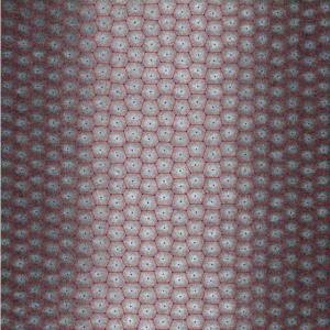
I've attached an example where I've overlaid the centers of the atomic columns (blue dots) and the voronoi tesselation (red vertices) on the original image.
Thank you for your help.


I hope this helps,
A.G.
WaveMetrics, Inc.
July 5, 2017 at 12:04 pm - Permalink
ImageBoundaryToMask was indeed the only missing ingredient.
July 13, 2017 at 07:51 am - Permalink
This is great!
However it seems that in some occasion the "seed" may not be within the boundary so an error occurs
"error: Bad seed pixel specification."
Here is a minimal code that may reproduce the error if run multiple times
Is there a straightforward test should be implemented on seedx and seedy to avoid the error ?
July 18, 2025 at 02:51 pm - Permalink
1. It is not obvious to me what is the purpose of executing WaveStats inside the loop. You have 1e6 points so unless you have a good reason, I'd skip that.
2. To figure out what is happening in any particular run you can execute:
and then expand the display until you can inspect the details.
In a normal application the input is rarely a uniform noise so that points are unlikely to "overlap". Here "overlap" is in quotes because in practice there is a minimum distance that is required between the seed and the boundary. Also, the operation was originally designed to work with integer pixels. When you apply wave scaling the code has to internally compute the corresponding pixels (some rounding is involved) which, as you can see here, leads to seeds falling on the boundary.
Depending on your goal in this calculation you may want to apply a completely different wave scaling; increasing the number of pixels in the mask improves the resolution and accuracy of the results.
AG
July 21, 2025 at 11:33 am - Permalink